|
Low Pressure Co2 Fire Extinguishing Equipment |
 |

 |
Introduction to the Low Pressure co2Automatic Fire Extinguishing Equipment |
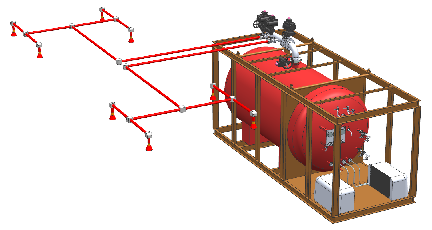
In addition, it is also featured with the Co2 inerting function based on the low pressure Co2 automatic fire-extinguishing system, and thus is a specialized device for reduction of explosive concentration in cement manufacturing and power generation. It is characterized as comprehensive functionality, good automation performance, reliable and accurate operation, etc. It is mainly composed of the inerting master valve, vaporizer, pressure reduction device, inerting selector valve, magnetic valve, refrigeration unit, inerting device control cabinet, nozzle, pipe and pipe accessory, etc. After receiving the release signal from the protection zone or the central control room, it can timely vaporize the release Co2, reduce the pressure and distribute the vaporized carbon dioxide to the protection zone which requires inerting to reduce the explosive concentration in the protection zone, and this process generally lasts for 8 hours.
QMED series low pressure Co2 equipment is characterized as reliable and secure actuation, convenient operation, ease of installation, reset and maintenance & repair, etc. The system can provide automatic monitoring and continuously display pressure and liquid level, and is designed with automatic alarm of high/low pressure and high/low liquid levels. Its refrigerator can be started and shut automatically. The turn-on and turn-off time of the master valve and the selector valve can be controlled by programming based on the size of the protection zone, to realize the objective of reliable fire extinguishing.
In conclusion, the low pressure Co2 system will be increasingly popular in the market thanks to its high efficiency, low cost, free of pollution, wide range of application and superior expandability, etc.
|
|
|
 |
Main parameters of the equipment: |
|
Model |
Design pressure (MPa) |
Extinguishing agent storage temperature (℃) |
Filling rate (kg/l) |
Operating temperature (℃) |
Working voltage (V) |
Refrigeration unit |
|
QMED-6.7-W/P-SA |
2.5 |
-20--18
|
≤0.95
|
-23-+50
|
AC220/380 DC24±3 |
Dual refrigeration |
|
QMED-11.1-W/P-SA |
2.5 |
-20--18 |
≤0.95 |
-23-+50 |
AC220/380 DC24±3 |
Dual refrigeration |
 |
Parameters of the refrigeration unit |
|
Refrigeration unit Model |
Refrigerant |
Nominal horsepower (hp) |
Net weight (Kg) |
Operational current (A) |
Maximum current (A) |
Voltage (V) |
Input power (W) |
|
TAG2516ZBR |
R404A |
4 |
106 |
5.18 |
10.7 |
380 |
3151 |
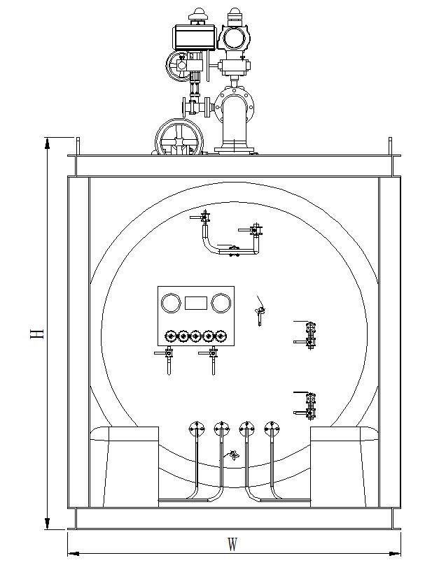
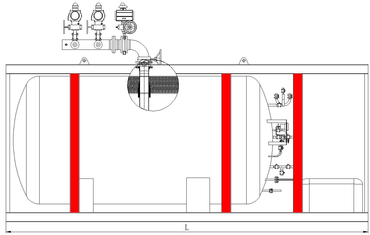
Shape and connection dimensions of storage tank
|
Tonnage (t) |
L1 (mm) |
L2 (mm) |
H1 (mm) |
H2 (mm) |
Gross weight (including extinguishing agent) (t) |
Emission caliber (mm) |
|
6 |
6300 |
2400 |
2900 |
11 |
150 |
6 |
|
10 |
8500 |
2400 |
2900 |
16 |
150 |
10 |
 |
The components of the fire-extinguishing system: |
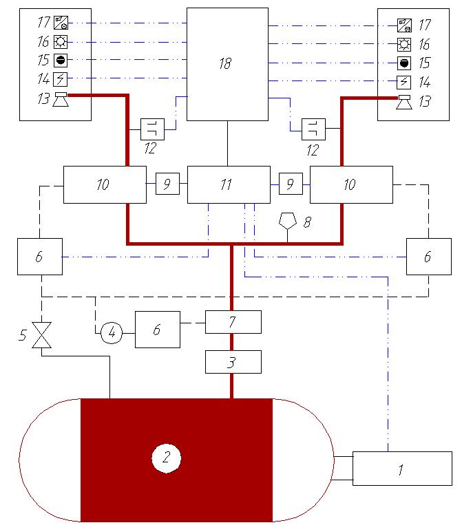
Designations of the main components and the function table:
|
Serial No. |
Name |
Function |
|
1 |
Refrigeration unit |
It ensures that the Co2 extinguishing agent in the storage tank is in a low temperature and low pressure state in the long term. |
|
2 |
Storage tank |
It stores the Co2 extinguishing agent in low temperature and low pressure. |
|
3 |
Maintenance valve |
Normally open, and closed upon overhaul of the master valve. |
|
4 |
Pressure reducing valve |
It reduces the pressure of the air source in the pipeline that controls the master valve. |
|
5 |
Start-up pipeline maintenance valve |
Normally open, and closed upon overhaul of the start-up pipeline |
|
6 |
Magnetic valve |
It controls on and off of the master valve and the selector valve. |
|
7 |
Master valve |
Normally closed, and opened upon fire extinguishing to release the Co2 extinguishing agent. |
|
8 |
Safety relief valve |
When the pressure in the system's pipeline is excessively high, the diaphragm blasts to protect the system. |
|
9 |
Pressure switch |
It sends the signals of opening and closing statuses of the selector valve to the control cabinet. |
|
10 |
Selector valve |
It controls the Co2 extinguishing agent to flow to the protection zone which needs extinguishing. |
|
11 |
Control cabinet |
It provides status monitoring of the storage tank, and executes the extinguishing command. |
|
12 |
Self-locking pressure switch |
When the extinguishing agent is released, it sends the extinguishing agent release signal to the alarm extinguishing controller. |
|
13 |
Nozzle |
It ejects Co2 extinguishing agent for fire extinguishing. |
|
14 |
Fire detector |
It detects fire and sends fire signal to the alarm extinguishing controller. |
|
15 |
Manual control box |
It realizes manual operation and emergency stop operation of the system. |
|
16 |
Gas release display |
It alerts people in the site that the Co2 extinguishing agent is released |
|
17 |
Sound and light alarm |
It sends sound-light alarms once the system detects fire. |
|
18 |
Alarm extinguishing controller |
It provides fire alarming and sends fire extinguishing command. |
 |
The components of the inerting system: |
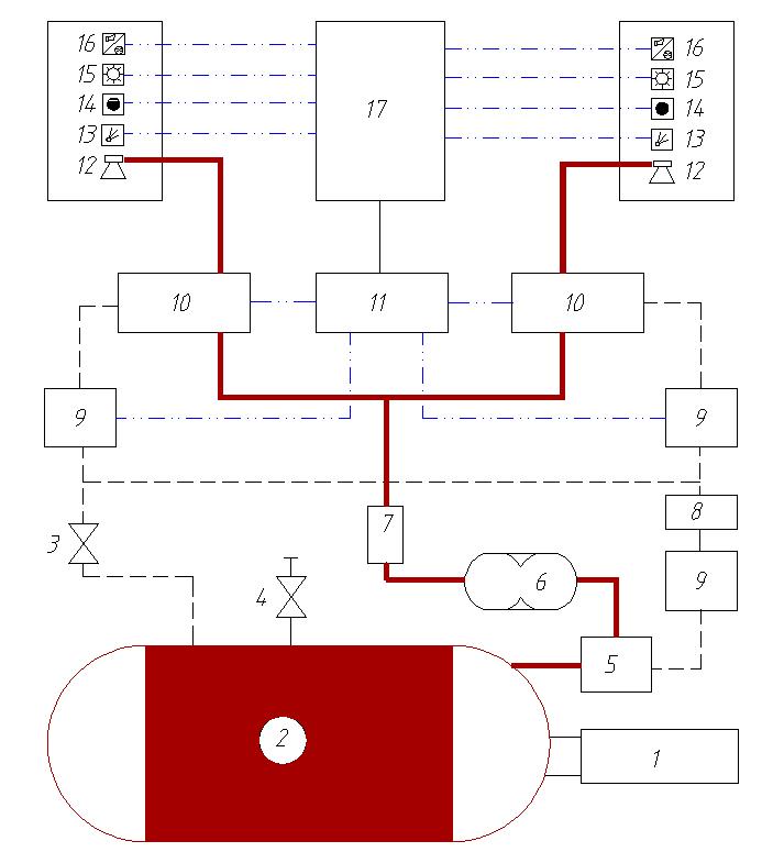
Designations of main components of the low pressure Co2 inerting equipment and their functions are shown in the following table:
|
Serial No. |
Name |
Function |
|
1 |
Refrigeration unit |
It ensures that the Co2 extinguishing agent in the storage tank is in a low temperature and low pressure state in the long term. |
|
2 |
Storage tank |
It stores the Co2 extinguishing agent in low temperature and low pressure. |
|
3 |
Start-up pipeline maintenance valve |
Normally open, and closed upon overhaul of the start-up pipeline |
|
4 |
Safety relief valve |
When the pressure in the system's pipeline is excessively high, open the protection system. |
|
5 |
Inerting master valve |
Normally closed, and opened upon inerting to release the Co2 extinguishing agent. |
|
6 |
Vaporizer and controller |
It provides heat preservation in normal cases, and provides heating upon inerting to generate sufficient heat |
|
7 |
Pressure reduction device |
It is at the servo status in normal cases, and can cancel pressure reduction in emergencies. |
|
8 |
Pressure reducing valve |
It is at the servo status in normal cases, to reduce pressure in the inerting master valve's cylinder. |
|
9 |
Magnetic valve |
It controls opening and closing of the inerting master valve and the inerting selector valve. |
|
10 |
Inerting selector valve |
It controls the Co2 extinguishing agent to flow to the protection zone which needs inerting. |
|
11 |
Inerting device control cabinet |
It provides status monitoring of the storage tank, and executes the inerting command. |
|
12 |
Nozzle |
It ejects Co2 extinguishing agent for fire inerting. |
|
13 |
Combustible gas detector |
It detects the concentrate of the flammable gas in the protection zone, and sends feedback of out-of-limit concentrate to the inerting controller. |
|
14 |
Manual control box |
It realizes manual operation and emergency stop operation of the system. |
|
15 |
Gas release display |
It alerts people in the site that the inert gas is released. |
|
16 |
Sound and light alarm |
It sends sound-light alarms once the system detects out-of-limit concentrate. |
|
17 |
Alarm controller |
It is at the alarm servo status to receive and transmit inerting signals. |
Notes: 1. We can customize the produce for various specifications based on customer requirements.
2. Since the low pressure Co2 fire extinguishing equipment is sophisticated, please contact us via mail or telephone for more details, and we will be honored to serve you


